18 Domains and boundary conditions
Domains, boundary conditions, MRF, and mesh motion
18.1 What this setting is
A domain is a computational region that assigns physical meaning and material properties, such as fluid or solid, to a mesh zone. Boundary conditions define how flow enters or leaves at a domain’s outer faces (markers), meets a wall, or satisfies symmetry and farfield conditions. As in CFX, think of creating a region first and then attaching conditions to its boundaries; this safely connects mesh names to the analysis model.
18.2 Configure in the GUI
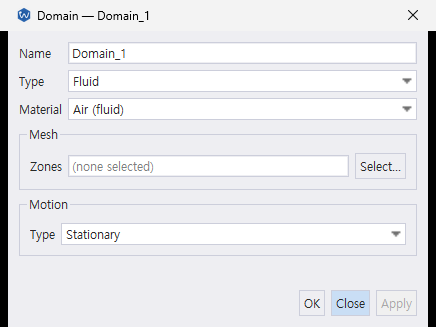
Create the domain first, select its material and mesh zones, and then add boundary objects beneath it. The boundary editor changes its fields according to the selected boundary type. The resulting names are used by domains[].mesh_zones and domains[].boundaries[].mesh_markers in JSONC.
18.3 Configure in JSONC
{
  "domains": [
    {
      "name": "fluid",
      "type": "fluid",
      "material": "Air",
      "mesh_zones": ["fluid_zone"],
      "boundaries": [
        {
          "name": "airfoil", "type": "wall", "mesh_markers": ["AIRFOIL"],
          "momentum": "free_slip", "heat": "adiabatic"
        },
        {
          "name": "farfield", "type": "farfield", "mesh_markers": ["FARFIELD"],
          "mach": 0.8, "pressure": 101325.0, "temperature": 273.15,
          "flow_direction": [1.0, 0.0, 0.0]
        }
      ]
    }
  ]
}| Key | Meaning |
|---|---|
type |
fluid or solid (CHT) — see domain.type below |
material |
References a materials[].name |
mesh_zones |
Required array of mesh-zone names — see mesh_zones below |
boundaries |
Array of tagged-union boundary conditions — see Boundary conditions below |
v0.4.0 breaking changes
locations→mesh_zones(domain) /mesh_markers(boundary, interface)mesh_zonesandmesh_markersare always string arrays (for example,["Zone1"])
18.4 domain.type
| Value | Status |
|---|---|
fluid |
production |
solid |
CHT (d0107) |
18.5 mesh_zones
Accepts a zone name, scoped name (scope/zone), or volume-region name. It is required with MRF as well, for grid_velocity assignment.
{ "mesh_zones": ["Zone1"] }
{ "mesh_zones": ["ROTOR_ZONE", "ROTOR_TIP"] }
A single zone, or several for a domain spanning multiple mesh regions.
18.6 motion (MRF, Multiple Reference Frame)
Assign a rotating coordinate frame to the entire domain:
{
  "domains": [
    {
      "name": "rotor", "type": "fluid", "material": "Air",
      "mesh_zones": ["ROTOR_ZONE"],
      "motion": {
        "type": "rotating",
        "omega": -1340.5,
        "axis": [0, 0, 1],
        "center": [0.0, 0.0, 0.0],
        "mesh_motion": false
      }
    }
  ]
}| Key | Unit | Meaning |
|---|---|---|
type |
— | stationary (default) or rotating |
omega |
rad/s | Signed rotation rate (rpm × 2π/60) |
axis |
— | Rotation axis (unit vector, auto-normalized) |
center |
m | Rotation center |
mesh_motion |
— | false (default) = MRF frozen rotor — grid stays fixed, only the reference-frame transform is applied (steady, pairs with interfaces[].type: "frozen_rotor" or ggi). true = sliding mesh — the grid is actually rotated each step (unsteady dual-time only, pairs with interfaces[].type: "sliding"). |
18.7 Boundary conditions (nine-type tagged union)
| Category | type |
Meaning |
|---|---|---|
| topology | wall |
Wall surface |
| topology | farfield |
Farfield boundary (characteristic-based) |
| topology | symmetry |
Symmetry plane |
| topology | internal |
Internal interface face (no BC treatment) |
| inlet | pressure_inlet |
Total-pressure inlet (P0, T0, flow_direction) |
| inlet | velocity_inlet |
Velocity-component inlet |
| inlet | mass_flow_inlet |
Mass-flow inlet |
| outlet | pressure_outlet |
Back-pressure outlet |
| outlet | mass_flow_outlet |
Mass-flow outlet |
Interface boundaries are separate
Define periodic, stage, frozen_rotor, sliding, and cht in the interfaces: section.
18.7.1 Wall
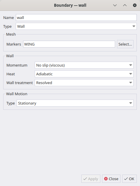
{
  "name": "airfoil", "type": "wall", "mesh_markers": ["AIRFOIL"],
  "momentum": "free_slip",
  "heat": "adiabatic",
  "wall_treatment": "resolved",
  "motion": { "type": "stationary" }
}| Key | Meaning |
|---|---|
momentum |
free_slip (Euler) or no_slip (NS/RANS) |
heat |
adiabatic, isothermal (add temperature [K]), or heat_flux (add heat_flux [W/m²]) |
wall_treatment |
resolved or automatic. DBNS RANS no-slip walls default to automatic except axisymmetric cases; other routes default to resolved. |
motion |
Tagged union, NS no-slip only — see Wall motion below |
Wall function (per-marker)
Setting wall_treatment: "automatic" enables the model-specific wall law on that marker. Configure shared constants in models.wall_treatment. The old wall_function key and y_plus_min threshold were removed. Resolved treatment requires a mesh that resolves the viscous sublayer.
18.7.1.1 Wall motion (NS no-slip only, tagged union)
"motion": { "type": "stationary" }"motion": { "type": "translating", "velocity": [10.0, 0.0, 0.0] }"motion": { "type": "rotating", "omega": 157.08, "axis": [0, 0, 1], "center": [0, 0, 0] }type |
Fields | Unit |
|---|---|---|
stationary (default) |
— | — |
translating |
velocity — [x, y, z] vector |
m/s |
rotating |
omega (signed), axis (unit vector), center |
rad/s, —, m |
Wall velocity components are absolute-frame values. Omitting motion on the no-slip wall of a rotating domain means the wall turns with the domain; give stationary for a fixed casing.
18.7.2 Farfield
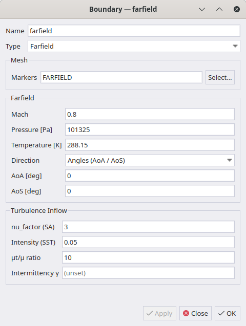
farfield is for remote boundaries only.
Use farfield only on faces where a uniform freestream assumption is valid. Using it on a face crossed by a boundary layer or shear flow, such as a wind-tunnel outlet, creates a spurious pressure gradient. In one flat-plate validation, near-wall dP/dx reached −73 Pa/m and downstream Cf was six percentage points too high.
For wind-tunnel-style cases, use pressure_inlet (total conditions) with pressure_outlet (static pressure).
{
  "name": "farfield", "type": "farfield", "mesh_markers": ["FARFIELD"],
  "mach": 0.8,
  "pressure": 101325.0,
  "temperature": 273.15,
  "aoa": 1.25,
  "aos": 0.0,
  "turbulence": {
    "nu_factor": 3.0,
    "intensity": 0.05,
    "eddy_viscosity_ratio": 10.0,
    "intermittency": 1.0
  }
}| Key | Unit | Meaning |
|---|---|---|
mach |
— | Freestream Mach number |
pressure, temperature |
Pa, K | Static reference state (density is derived through the EOS) |
aoa |
° | Angle of attack, −180 to 180: 2D rotates in x–y, 3D in x–z |
aos |
° | Sideslip angle, −90 to 90; omit or set to 0 in 2D |
flow_direction |
— | [x, y, z] unit vector, normalized on read; the alternative to aoa/aos |
turbulence.nu_factor |
— | SA only: ν̃_inf = nu_factor · ν_lam |
turbulence.intensity |
— | SST/k-ω only: freestream turbulence intensity (0.05 = 5%) |
turbulence.eddy_viscosity_ratio |
— | Freestream turbulent/laminar viscosity ratio μ_t/μ; length_scale [m] and hydraulic_diameter [m] are alternatives, and only one may be given |
turbulence.intermittency |
— | Transition intermittency γ (LM transition model) |
Flow direction: Give aoa (with aos in 3D) when you have angles, or flow_direction when you already have the vector. One of the two is required in the Mach form — a far field without either is rejected. A non-zero aoa/aos overrides flow_direction, so supply one form, not both. Both are plain numbers here; expressions apply to the state values, not to the direction.
FR-only fields
Two further fields apply only under analysis.solver=fr: characteristic (compressible path — true switches this farfield to a low-reflection characteristic Riemann invariant BC instead of a fixed freestream ghost state; default false), and, only under models.regime=incompressible (the AC track), velocity (|V|, consumed by the AC characteristic BC), ac_zeta, and ac_niters (AC Newton-iteration count for the characteristic solve; default 4).
18.7.2.1 Direct primitive-variable input
When rho, u, v, w, and p are provided, these values are used instead of deriving the state from (Mach, P, T); supplying both forms on one boundary is rejected. Each value may be a constant or an expression in x, y, z, and t. If any value is an expression, the boundary condition becomes space- and time-dependent and is reevaluated at every stage.
{
  "name": "inflow", "type": "farfield", "mesh_markers": ["INLET"],
  "rho": 1.0,
  "u":   { "type": "expression", "expr": "1.0 + 0.1*sin(2*pi*t)" },
  "v":   0.0,
  "w":   0.0,
  "p":   1.0
}With this form, the farfield is excluded from nondimensional reference-state extraction. The reference block or another farfield must define the reference.
18.7.3 Symmetry
{ "name": "sym", "type": "symmetry", "mesh_markers": ["SYM"] }18.7.4 Internal
{ "name": "rs_interface", "type": "internal", "mesh_markers": ["INTERFACE"] }Internal mesh interface face: no BC treatment and no vertex_normal calculation.
18.7.5 pressure_inlet: total-pressure inlet
{
  "name": "inlet", "type": "pressure_inlet", "mesh_markers": ["INLET"],
  "formulation": "dirichlet",
  "total_pressure": 120000.0,
  "total_temperature": 300.0,
  "direction_type": "cartesian",
  "flow_direction": [1.0, 0.0, 0.0],
  "turbulence": { "intensity": 0.03, "eddy_viscosity_ratio": 10.0 }
}| Key | Unit | Meaning |
|---|---|---|
formulation |
— | dirichlet (default, algebraic), riemann (characteristic), or giles (1D NRBC) |
total_pressure, total_temperature |
Pa, K | Total (stagnation) conditions P0, T0 |
direction_type |
— | cartesian (default, reads flow_direction), normal (inward face normal), or cylindrical (reads the cyl_* keys, see below). aoa/aos are rejected on an inlet |
flow_direction |
— | [x, y, z] unit vector; needed when direction_type is cartesian |
relaxation |
— | Giles NRBC relaxation factor, only used with formulation: "giles" |
18.7.5.1 Cylindrical inlet (turbomachinery)
{
  "name": "inlet", "type": "pressure_inlet", "mesh_markers": ["INLET"],
  "total_pressure": 120000.0,
  "total_temperature": 300.0,
  "direction_type": "cylindrical",
  "cyl_axis": [0, 0, 1],
  "cyl_center": [0, 0, 0],
  "cyl_axial": 1.0,
  "cyl_tangential": 0.5,
  "cyl_radial": 0.0
}
direction_type is cartesian (reads flow_direction), normal (face-normal), or cylindrical. The cylindrical form takes cyl_axis through cyl_center plus the cyl_axial/cyl_tangential/cyl_radial component ratios — not m/s, as the magnitude comes from the inlet’s own total conditions. Positive cyl_tangential is right-handed about cyl_axis.
18.7.6 velocity_inlet: velocity-magnitude inlet
{
  "name": "inlet", "type": "velocity_inlet", "mesh_markers": ["VEL_INLET"],
  "velocity": 50.0,
  "flow_direction": [1.0, 0.0, 0.0],
  "pressure": 101325.0,
  "temperature": 300.0
}| Key | Unit | Meaning |
|---|---|---|
velocity |
m/s | Inflow speed, 0 or greater. Required |
flow_direction |
— | [x, y, z] unit vector. Required |
pressure, temperature |
Pa, K | Optional static reference |
Under DBNS velocity and temperature also accept expressions, in x, y, z for a per-vertex profile. PBNS takes numbers only.
18.7.7 mass_flow_inlet: mass-flow inlet
{
  "name": "inlet", "type": "mass_flow_inlet", "mesh_markers": ["MF_INLET"],
  "mass_flow": 2.5,
  "total_temperature": 300.0,
  "direction_type": "cartesian",
  "flow_direction": [1.0, 0.0, 0.0]
}
mass_flow [kg/s] and total_temperature [K] are both required; the direction uses the same direction_type and flow_direction / cyl_* keys as pressure_inlet. Total pressure is an outcome here, so the case still has a solution when the downstream chokes. DBNS, ideal_gas, and formulation: "dirichlet" only.
18.7.8 pressure_outlet: back-pressure outlet
{
  "name": "outlet", "type": "pressure_outlet", "mesh_markers": ["OUTLET"],
  "formulation": "dirichlet",
  "back_pressure": 101325.0,
  "supersonic": false
}| Key | Unit | Meaning |
|---|---|---|
formulation |
— | dirichlet (default), riemann, or giles — same meaning as pressure_inlet above |
back_pressure |
Pa | Static back pressure |
supersonic |
— | Supersonic-outlet treatment (extrapolate everything, ignore back_pressure) |
relaxation |
— | Giles NRBC relaxation factor, only used with formulation: "giles" |
18.7.8.1 Outlet averaging (CFX-style)
{
  "name": "outlet", "type": "pressure_outlet", "mesh_markers": ["OUTLET"],
  "back_pressure": 101325.0,
  "averaging": {
    "type": "circumferential",
    "blend": 0.0,
    "n_span": 32,
    "axis": [0, 0, 1],
    "center": [0, 0, 0]
  }
}| Key | Meaning |
|---|---|
type |
average or circumferential |
blend |
β ∈ [0,1]: 0 = uniform, 1 = CFX-style |
n_span |
Number of circumferential bins (circumferential only) |
axis, center |
Rotation axis and center for the circumferential average |
18.7.9 mass_flow_outlet: mass-flow outlet
{
  "name": "outlet", "type": "mass_flow_outlet", "mesh_markers": ["MF_OUTLET"],
  "mass_flow": 2.5
}
mass_flow [kg/s] is the target rate.